New users frequently ask questions about how to set a program zero for a toolpath. Most will just accept the defaults and see what happens. Luckily, the default program zero in MeshCAM is very safe, and most users begin with very forgiving jobs, so everything usually works out fine. Once you get a few jobs done and get a better understanding of the process there are real benefits to picking the right program zero for a job.
My one caveat for this post is that it doesn’t apply equally to everyone; if you have a big machining center with an automatic tool changer and properly configured tool offset tables then this doesn’t apply to you as much.
A quick definition
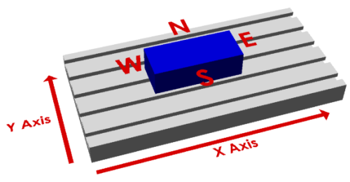
It’s difficult to write clearly about sizes and edges when we talk about the location of the zero. MeshCAM uses the compass layout- north, south, east, and west, to describe the location. This can be seen more clearly in the image below:
The purpose of the zero
At a basic level, the program zero tells the mill where to find the stock on it’s table. Since the mill table is generally much bigger than the stock you are cutting the mill must be “told” where you’ve put the stock. Without this registration process, there is very little chance that anything would line up.
The program zero also gives the CAM software a single reference point for the toolpath. On a mathematical level, the CAM program can accept any arbitrary zero point, it’s just an offset in space and one is as good as another. For you, the machinist, the program zero must be something you can locate with the mill; if the point cannot be located then you are probably going to have a lot of problems.
Location, location, location
Imagine, for instance, a zero that was 10 inches to the left of the bottom corner of the stock. While this is a point that does exist, it’s in empty space so you have very little change of accurately finding it.
By contrast, if you were to pick a corner of the stock then you have three planes/sides that you can touch the tool off of, the top, side, and front.
While this zero may take a few minutes for a new machinist to locate, it’s not hard to do if you’re patient.
The best default position
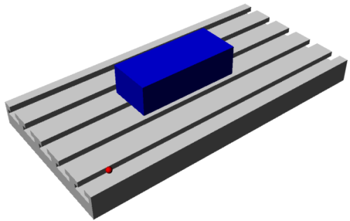
If I had to give you one default position to pick it would be the top of the stock, in the lower left-hand corner, the southwest corner in MeshCAM terminology. In general, this is what I use 90% of the time; it works well, it’s easy to locate and it keeps all of the X and Y toolpath coordinates as positive numbers. Z coordinates will be negative when you’re cutting into the stock and any positive Z number should be “in the air”. The only time the “Top Southwest” position may give you trouble is when you need to change tools…
What about tool changes?
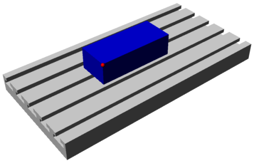
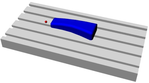
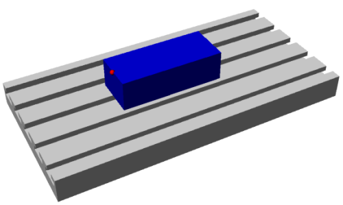
All of the coordinates in the gcode file tell the mill where to move the tip of your tool. If you change tools in the middle of a machining job then you need to reset the Z value of the zero since the two tools are not likely to be exactly the same length. The point you pick for a zero must be available any time you need to do a tool change and reset the tool length. If the point initially used has been machined away by the roughing operation then you’ve lost the ability to set your tool length. Image that you’ve set the zero on the top, southwest corner as seen below:
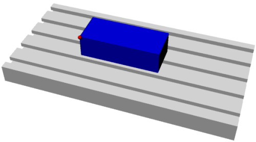
Nor you’ve finishing roughing and you’d like to use a different tool for the finishing. You need to touch off that corner again except that it isn’t there:
In many machine controllers it is possible to preconfigure everything so that a tool change doesn’t require a rezero. This option requires very accurate tool holders that keep the length constant and a lot of effort on your part to measure and input all of the length data before machining begins. In my experience, very few people do this.
The one saving grace here is that you really only need to recover the Z value and you might be able to recover that from a different section of the stock or as an offset from the table, if you knew the original thickness of the stock with sufficient accuracy.
So where should the zero be?
Well, there’s no single answer but none of them are very difficult. Here are a couple of things to keep in mind each time:
- Will the zero be there when you need to change a tool?
- If not, is the stock and machine flat enough that you can locate a different point and apply an offset?
- Maybe it’s easier to just machine the whole thing with a single tool and not worry about a rezero for a tool change. This is usually not the right answer but I’ll admit to doing it when I just want to get something done quickly.
Those three criterion are good enough most of the time and most users will never have to go beyond that.
Special Case - Two-Side Jobs
Two-side jobs are a special case in MeshCAM. It will do the bulk of the mental gymnastics to cut two sides of a part and give you two gcode files; one for the front and one for the back. The tradeoff is that you must provide MeshCAM with very accurate measurements of the stock so it can do the calculations on both sides. The whole process also requires you to remove the stock half way and flip it over to machine the back. While neither of these requirements is particularly daunting it does impose additional burdens on you as the machinist.
Below is what a cross section of the part might look like after a two-side machining job

If you do not accurately measure the stock or if you do not accurately put the stock back on the mill you are likely to end up with the following cross section:
This is completely avoidable if you spend the time to prepare the mill and the stock. First, align your vise or jig as perfectly as you can to the mill. Second, prepare the stock so that it is as square as you can make it and that you have the most accurate measurements possible. The your choice of program zeros can help reduce the error caused by doing either of these less-than-perfectly.
If possible, it is important to set the zero on the top of the stock, on middle of the left edge (“West” in the MeshCAM terminology). The helps mitigate the effects of error in the measurements you’ve given to MeshCAM as well as some alignment problems.
The only difficulty here is that desired zero point that cannot be directly located; you have to find the top and bottom edges and then set the zero to be at the middle point that you calculate between the two of them. It is important to zero the Y axis before the X axis; this lets you find the left edge at the same Y position for both sides of the job. If your stock is not completely square then this will help correct for erroneous offsets between the two sides of the job.
It takes another minute to locate the zero but I have found the results to be completely worth the effort. It may not be completely clear why this matters right now but it will become more obvious after you go through the whole process once or twice.
Conclusion
In my experience, 90% of machining is know how to hold the stock down and how to locate the features you need to get reference points (and taking the time to do both right). Once you get the “zero problem” figured out and you understand all of your options then you’re already well on your way.