In the circle of engineers and companies that I interact with, most use SolidWorks as their CAD program. I do know one or two using Pro/E or NX but they’re the odd cases. A few years ago I had the need to move up from Rhino, a great CAD program that is a great match with MeshCAM, to a parametric CAD program. My desire to interact with all of these other users, and a great leasing deal at the time, led me to buy a copy of Solidworks. It has been a great tool to have and it works great with our CAM Software. Hopefully MeshCAM will be a first-choice when you need CAM for SolidWorks.
All of that being said, it’s worth noting a few “quirks” about SW that make it slightly trickier to get a file out of than a program like Rhino.
File Types
MeshCAM Accepts 3D files as STL or DXF (using 3D Faces). Of the two, STL is preferable since it is a more robust format and it is faster to read into MeshCAM.
STL is a file format originally developed for the 3D printer market that represents your models as a bunch of triangles. Some users worry that some accuracy will be lost in the triangulation but this is not really the case. As shown below, you can create the STL file to almost arbitrary accuracy- generally well beyond the accuracy of your mill. Second, most CAM programs that take SolidWorks files natively do this triangulation in the background, it’s just hidden from you. Lean more about how to convert STL to G-Code.
Workplanes
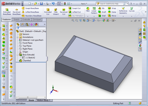
The first thing that many users note when taking the output from SolidWorks to CAM software is the orientation of the parts. As someone planning to machine a part after designing it, it’s tempting to build the part by extruding out from the “Top” plane.
When you load the resulting STL file into MeshCAM you’ll see the following:
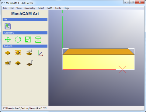
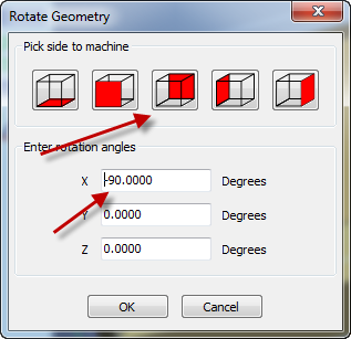
Obviously, this will require a rotation before machining it. Within MeshCAM you can use the “Rotate Geometry” command to get the correct orientation. You can enter an X rotation of “-90” or, if you’re running MeshCAM Version 5, click the face button below:
The simple option is to always extrude from the “Front” plane in SolidWorks. If you do, you will always be able to load the STL directly into MeshCAM without rotation.
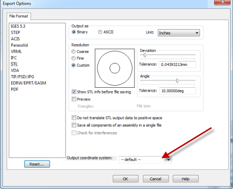
[EDIT] Randy just filled me on another technique that I never knew about- reference coordinate systems. Under your Insert->Reference Geometry menu, select Coordinate System. Place it in whatever location you want but align it so that the Z axis is parallel to the Z axis of your mill. When you open the STL Options window, pick that new coordinate system using the pull down shown here:
Your STL will now have the proper orientation without any need to rotate it within MeshCAM. Thanks Randy!
STL Units
Here’s a really frustrating thing in SolidWorks (if you don’t know about it)- the units of the STL are not necessarily the same as your part.
After you click “Save As” and select STL as the file type, click the “Options” button shown below.
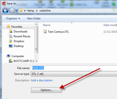
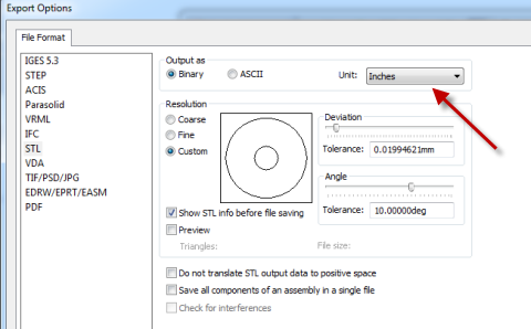
When you get the options window open, note the “Unit” setting:
The unit value selected here will be used in your STL file no matter what units are used in your part file. If they differ, the part will be converted to the STL units when you save it.
STL Quality
The other major setting that affects the STL output is the “Resolution” setting defined in the “Export Options” window shown above. The resolution values define how accurately the STL represents your original part file.
SolidWorks predefines a “coarse” and “fine” resolution and these will be fine for most users. Unless you have a very large model I would usually recommend starting with the “Fine” option.
SolidWorks also gives you the option to define your own quality level using the “Angle” and “Deviation” sliders. ”Angle” defines the maximum allowable angle between two triangles that originate from the same surface. If that threshold is exceeded, smaller triangles are used. The “Deviation” is the maximum allowable error allowable in the output. Put another way, “deviation” is the maximum distance that a triangle can be from the surface that it represents. For both settings, smaller values will give more accurate files at the expense of more triangles generate. MeshCAM can handle very large STL files so you can definately use settings that are beyond the predefined “Fine” values and still have no problems.
Watertight/Solid STL files
Here is my one complaint about SolidWorks- it will not save surfaces as STL files, it will only save watertight solids. To be fair, this is part of the STL standard and they follow that standard carefully. If you have a surface model you will not be able to save it as an STL without finding a way to make it into a solid.
For what it’s worth, most other CAD programs will generate STL files from surfaces and MeshCAM will happily machine them.
Conclusion
Hopefully this is enough to get new users over a few of the difficult starting points to get going with SolidWorks CAM. Be sure to post in the comments in there is anything else that should be added.