I get two questions over and over: “What is the surface angle limit?” and “Parallel finish leaves ragged edges, what can I do?” Each question is really the answer to the other but it’s something I’ve had a lot of trouble communicating. Here’s my latest attempt complete with pictures…
A Simple Geometry
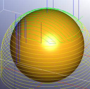
Below is a simple geometry that I’ve loaded into MeshCAM:
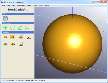
As you can see, it’s a very simple sphere but it has two very important characteristics that can be used to illustrate the benefits of the surface angle limit function, it has a relatively flat area on the top of the sphere and vertical walls at the edge when machined on a 3-axis mill. All toolpaths shown below will use a .25” ball mill with a .05” stepover and stepdown.
Unconstrained Parallel Finishing
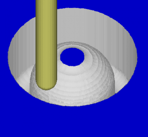
Below is what the toolpath looks like if we just use the parallel finish option:
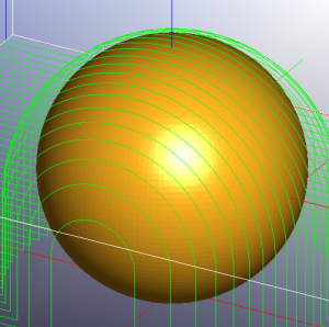
This is probably a very familiar-looking toolpath if you’ve spent any time with MeshCAM. If we simulate it in Cutviewer we get the following:
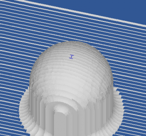
Note that the vertical edges are really rough while the top is relatively smooth. This illustrates the most important characteristic of parallel finishing: you get good results for shallow areas and poor results for steep areas. We could get a better finish on the whole part by reducing the stepover but that has a direct impact on machine time and machine time is something that most people strive to reduce.
Waterline Toolpaths
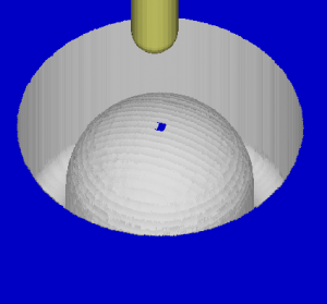
Waterline toolpaths are in many ways the exact opposite of parallel paths- you want them for the steep areas and want to avoid them for shallow areas. Here is the same part with a waterline toolpath:
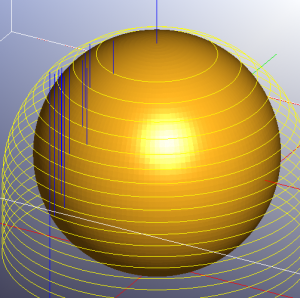
Note that the simulation shows the opposite of the parallel finish- the shallow top of the sphere is really rough and the steeper parts look good. As in the parallel, we can reduce the stepdown to get a better overall finish at the expense of machining time but that is never something to consider if you have other options.
It’s also easy enough to enable both parallel and waterline toolpaths at the same time to get a better finish but that is like reducing the stepover/stepdown- you are just trading the finish for machining time since musch of the geometry would be machine twice. Surely we can do better.
Combining Parallel and Waterline
This brings us to the point of this post, the “Surface angle limit” and “Min surface angle” settings:
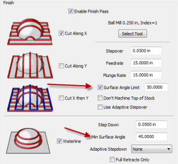
The purpose of these setting is to tell MeshCAM where to apply the parallel and waterline toolpaths. If the “Surface Angle Limit” parameter is enabled, only areas that are flatter than the defined angle will be machined with the parallel path. Likewise, only areas that are steeper than the “Min Surface Angle” value will be cut with the waterline toolpath. Generally I like to make them overlap slightly so there is no hard edge between the two in the finished part. Using the values above the toolpath looks like this:
That get’s us close to an ideal condition- steep areas with waterline, shallow areas with parallel and most of the geometry is machine only once. That’s as close to win-win as you can get.
The Short Version
Here’s a quick recap of why surface angle limits are such an important feature:
- Machine steep areas with waterline
- Machine shallow areas with parallel
- Only machine each part of the model once with no overlap
- Get the best finish possible without extending the machining time
For many users this should be something that is used on every job.